I have an Sunbeam Tiger (331 V8 with a race Carb), basically a race car now. I forgot to weld in the bungs for the O2 sensors at the collectors so my option being lazy was to purchase a couple of Innovate tail pipe clamp on for the sensor. It I have short turn downs right after the straight though mufflers with 3 inch pipe in and out.
I have heard from others that at the end of the exhaust the readings will be a bit on the leaner side. Any one use this type of set up? Using to set up idle and for static testing until I get the bungs welded in.
As long as there is no catalytic converter then it should be fine. During light load the lambda/afr might show leaner than reality as outside air maybe pulled into the clamp.
I have no cats on the car. Not sure how well the Innovate clamp will work, it’s pretty short, odd design, but no idea how well it will work but will keep an eye out ones I get it all going
It depends in your CAMshaft. If you place your Hand over the tailpipe and it sucks and pushes, the innovate clamp will Not Work well. It IS only usefull for exhausts with a steady outflow of exhausts Gas. Like you find IT with tame, Well muffled Cars or turbocharged ones.
Yeah, it’s a full race mechanical roller, so pretty healthy. That being said, it does not idle under about 1300 RPM so might help a bit.
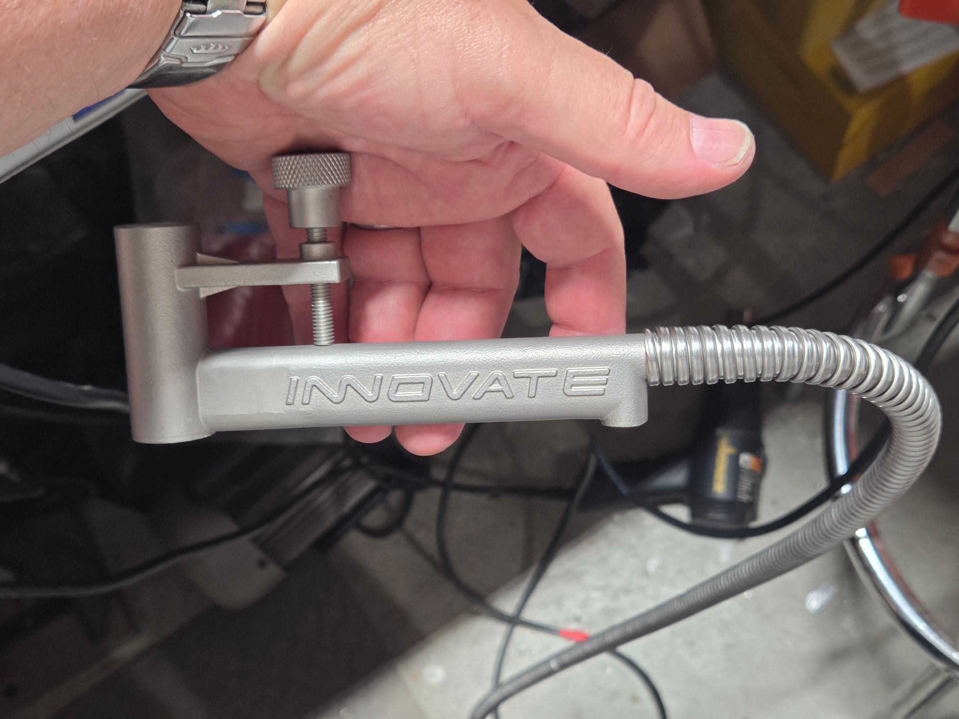
When I got the 2 Innovate pipe clap sensors I thought the same, it’s really short. I might try a piece of teflon braided steel line to clamp on the end to allow the probe point to be much further in, maybe 12” of teflon hose, or if I can find the spiral metal flex stuff (like old payphone handset metal cord) make something to help.
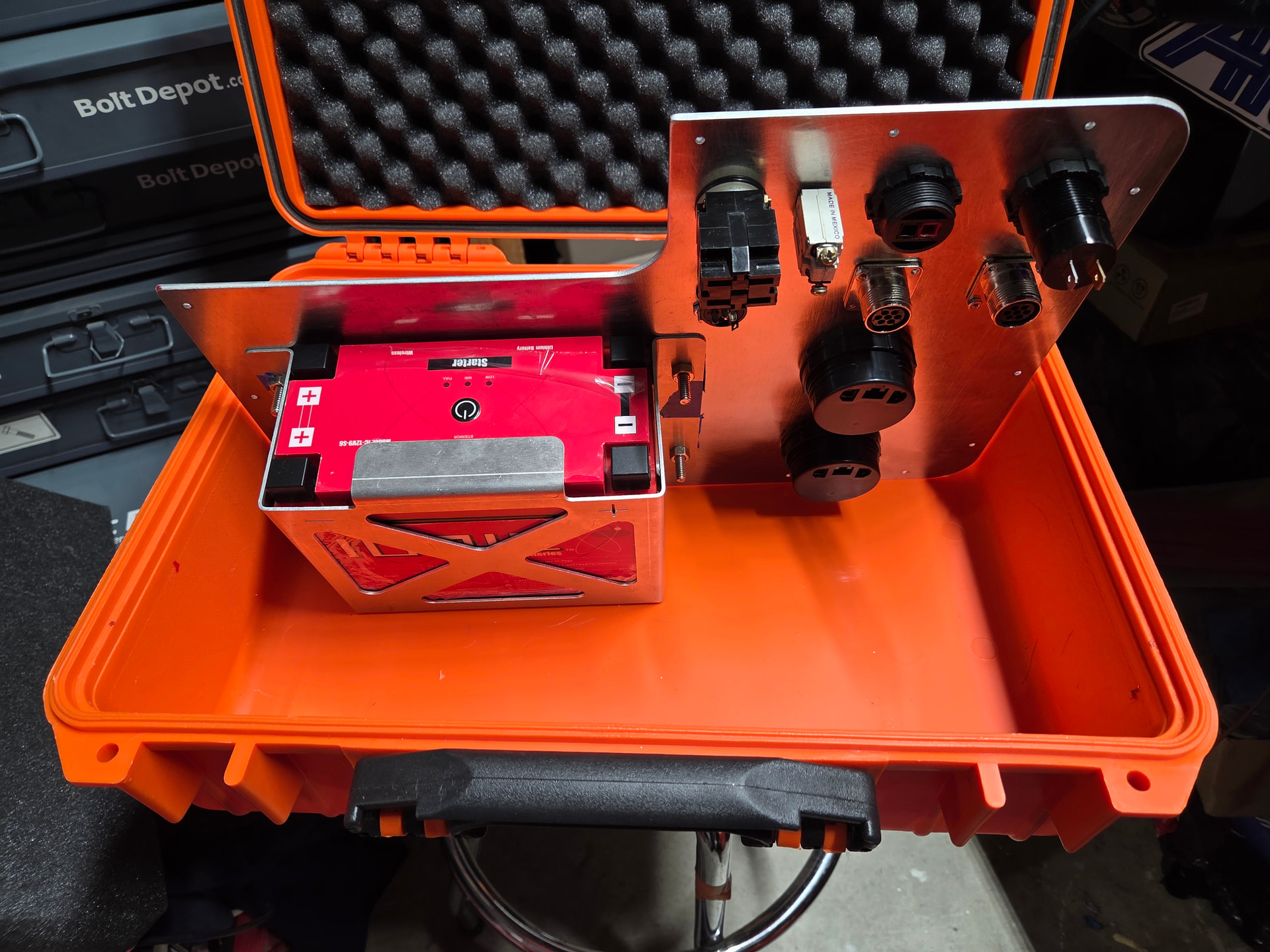
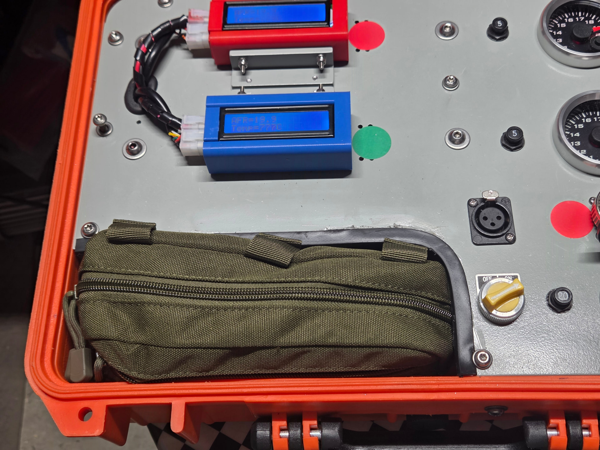
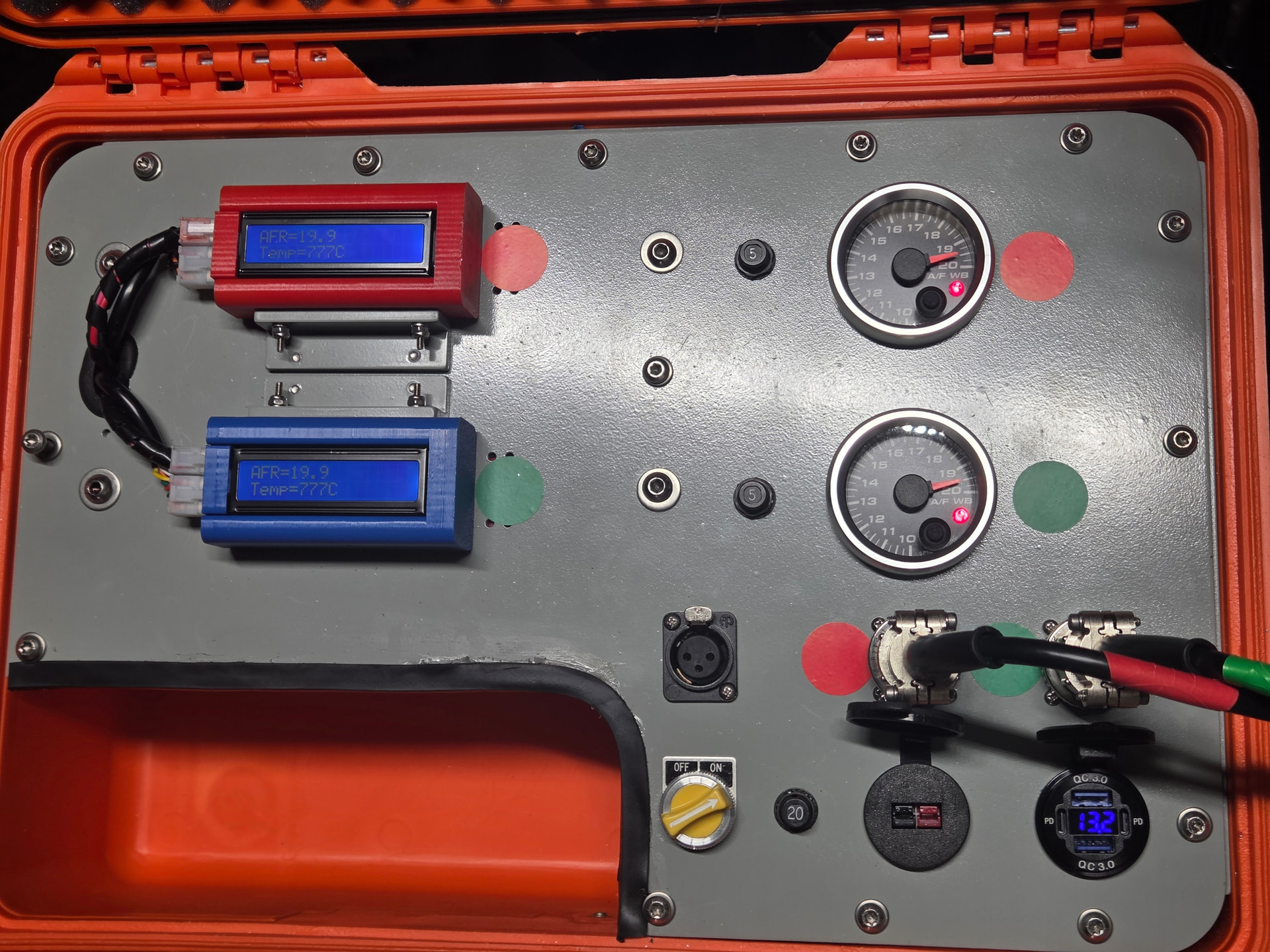
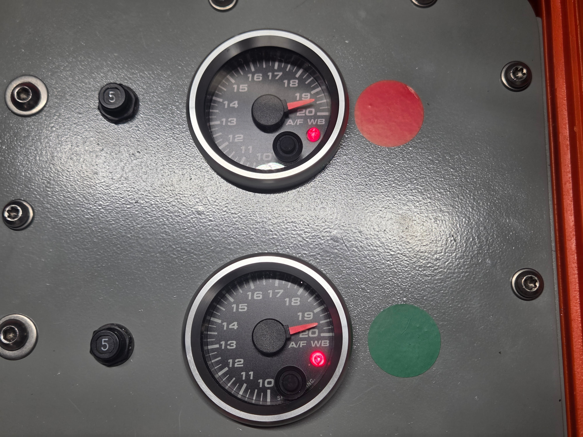
Work in progress, waiting on a couple of parts for the portable unit I’m making, but hopefully have most of what I need next week. The biggest problem is mounting the SLC to the case, but I think I have that solved. Hardware shown is just to hold things down until I can tap things.
I modified the innovative clamp with some stainless 3/8” (trade size) electrical flex from McMaster-Carr. Twisting it to enlarge it a bit makes it slide over the end of the clamp, then it springs tight so won’t fall off. Going to cut it at about a 1’ in length to help keep the reversion of air coming in, hopefully not too long to cause flow issues to the sensor. All 100% Experimental at this point.
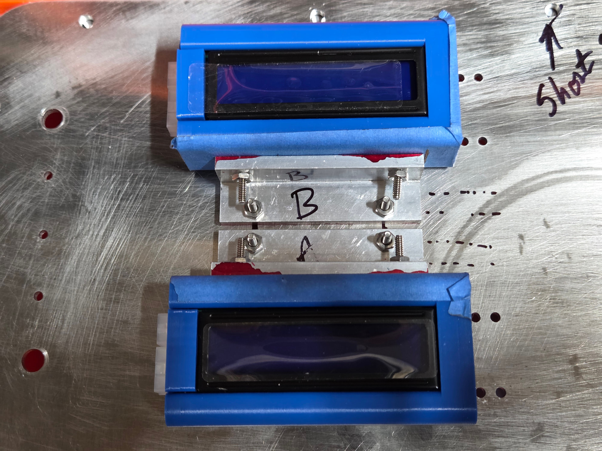
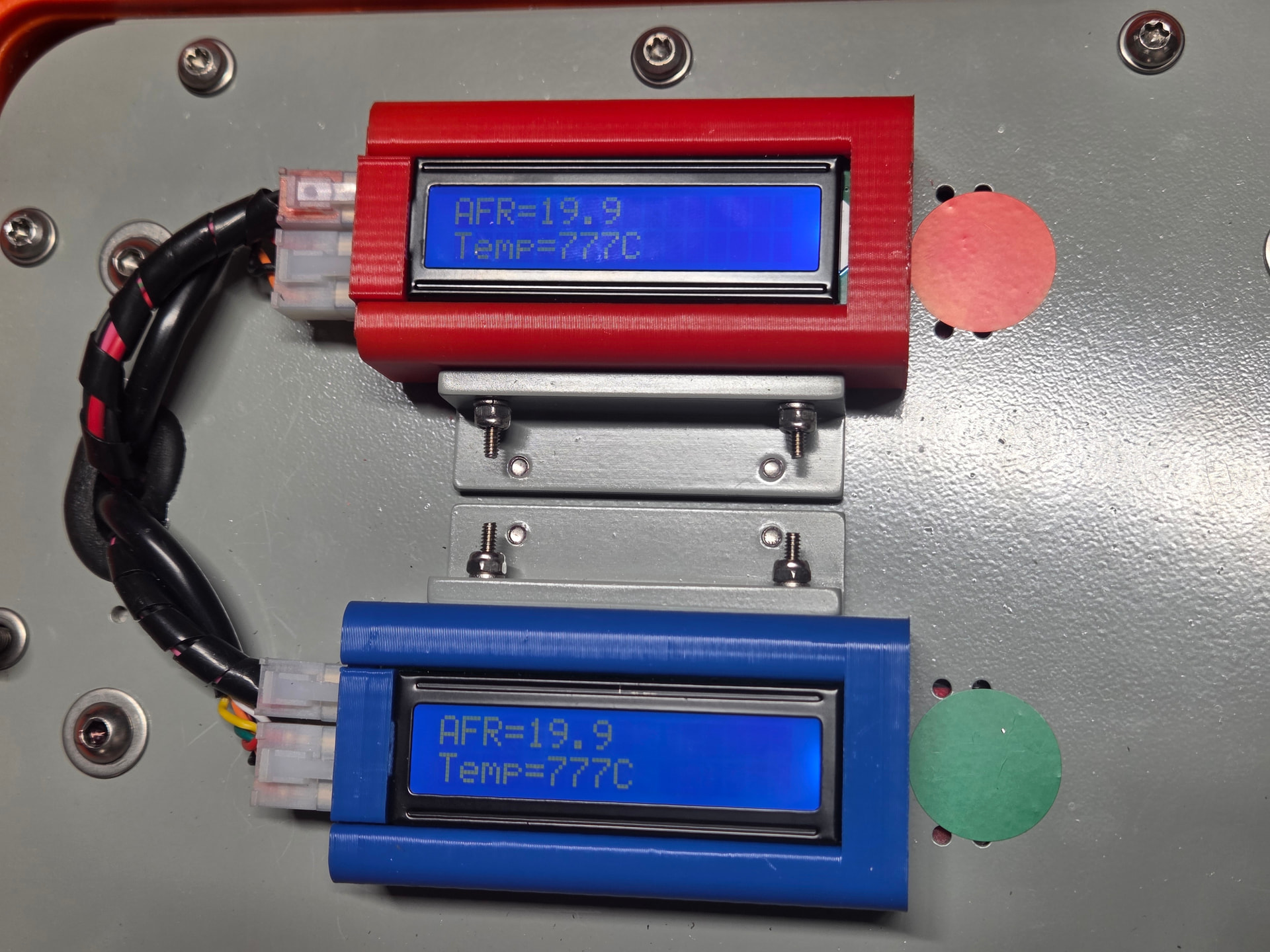
Wrapping up the project. But these controllers might be problematic with the analog output, they are off enough to be concerned.
@toalan any way to fix this, the mod didn’t seem to work fixing the offset.
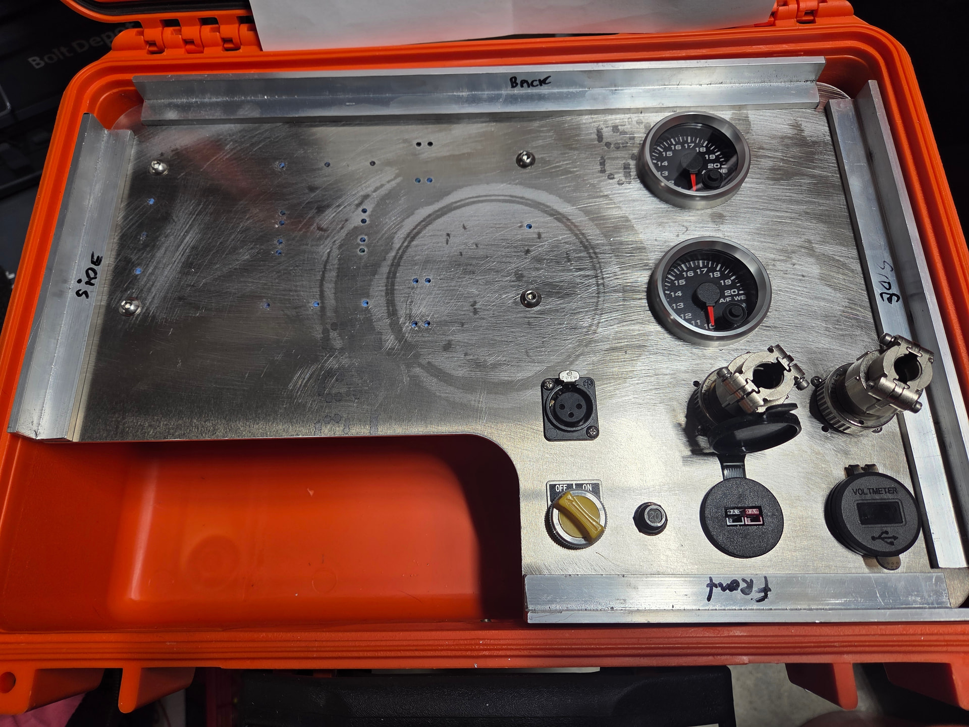
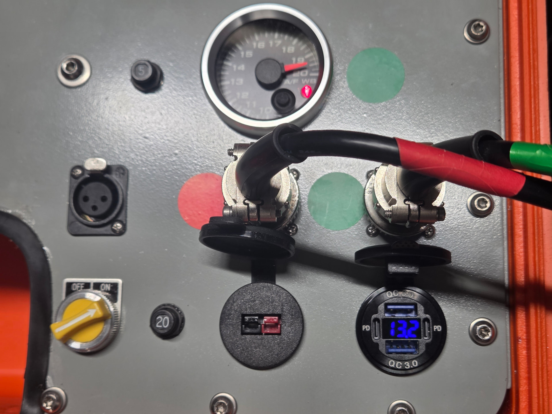
Connections to the WBO2 sensors, the charger port with the Anderson mini-powerpoles facilitate charging the internal battery, to the right is a voltmeter to monitor status of the battery (You can also do it via the Ionic app as well as other stats).
During power up the linear output will show 1.66v and then 3.33v, it should show up as 13.3 AFR and 16.66 AFR, verify that on your gauges. If there is significant difference, use a volt meter to measure the linear output to verify that the voltages at 1.66v and 3.33 v during startup.
I’m getting 1.514v and 3.055v on start up. I think I caught those check points. I will have to pull the panel apart and disconnect the gauge, possibly they are pulling down the voltage or something.
Got back in the garage for some testing, the old numbers were off due to a crappy Hantek DVM that I used, not far off but off enough. Pulled out the Fluke 177 and another Meter, and they were both matching and matching the power supply so I’ll say they are on.
New numbers, with gauges connected are 1.582vdc and 3.191vdc as the controllers start up. A little off of the first measurements in the earlier post but still off from what they should be.
Now with the info from Alan, I pulled the panel and unhooked the gauge, and magically the readings for start up are correct, now 1.66vdc and 3.56vdc.
So it seems the gauges pull down the output of the controller, not sure how it’s driven from the output of the controller, but the gauge pulls it down enough for it to be off . The values 1.66v-1.58v so around 0.08v not sure how that translates, but it’s off reading a bit richer in AFR then the digital part is.
@toalan anything on the controller that I can easily change (I have some SMD soldering tools), but not sure if it’s worth it.
Also not sure if you had any contact in the past with SpeedHut on the gauges, but the gauge loading is the cause of the problem.
Thanks for the OpAmp as a buffer suggestion. Might be an add on project at some point.
Questions on the Spartan 3’s, do they have buffered output for the gauges?
I have them (And some 2’s I think) and wonder if I will run into the same issue if using the SpeedHut gauges as a dash display in the car if directly connected to the output.
In that case might be worth making a few small PCB’s to do the task.
Thanks for the help on this, at least I know what the issue is!
@sganz how did you find the behaviour of the innovate sniffer with your (rather neat) extension?
I’ve tried playing with an innovate as is & my SLC Free 2 on a stock MGA with really worn carbs. At tickover the SLC says “off the scale lean”, which is a lie, so it’s sucking air in. at 1500 and up it looks believeable (goes from too rich, to insanely rich) and is impressively responsive, so it all works pretty much as I’d hoped.
I’m interested as to whether your extension worked - I’d be suspisious, as I think the innovate uses the gas flow over the downward hole just below the “E” to draw air in to the top hole - so the pressure difference between the two is important, but it might be enough, and if it works, I might get good tickover readings too…. so I’m keen to hear!
Honestly I have not tried it as yet. It may not do anything. What I should do is try it on my daily driver and see how it reads. It’s a 2023 Kia Telluride, so should have pretty consistent readings.
On the todo list. It’s going to be a bit since I have a stack of other projects to catch up on.