Normally the ground for the electronics and sensor heater is shared, this reduces the accuracy of the linear output due to ground offset caused by the sensor heater current. The sensor heater consumes 1-3 amps, the electronics consume about 0.1 amps. In this mod we will split the ground, one ground for the electronics and another ground for the sensor Heater.
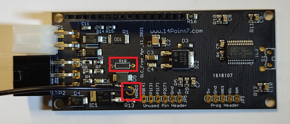
If you have a recent SLC Free 2 with the Black and gold PCB, remove R18 and solder a 20AWG or thicker wire to the pin with the name “HGND2”. The wire you just soldered is the sensor heater ground and the ground on the 4 pin Molex connector is your electronics ground.
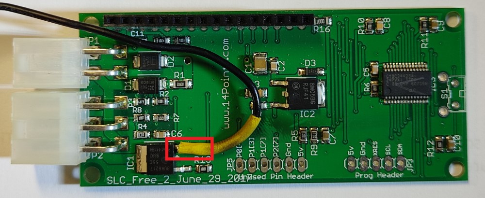
If you have an older SLC Free 2 with Green PCB, with a soldering iron lift the pin on IC1 from the pad, solder a 20AWG or thicker wire to that pin. Insulate the pin from the pad with heat shrink. Use adhesive or similar to secure the wire to the PCB as movement on the wire will rip the pin off IC1. The wire you just soldered is the sensor heater ground and the ground on the 4 pin Molex connector is your electronics ground.
The new heater ground wire should be wired to the chassis, the ground on the 4 pin Molex connector should be wired to the same ground as the device interfaced to the SLC Free 2’s Linear Output.
The electronics ground on the 4 pin molex connector should be grounded where the ECU is grounded. The new ground you just made should be grounded to chasis.
I will be using my slc free 2 to set up Harley pan heads and shovel head carbs, I will be using and external battery to power the slc how do you recommend I ground the system and the O2 heater ground.
There are not enough improvements in the black PCB to warrant me to release the PCB files. I do plan on releasing a new version of SLC Free, SLC Free 3, in the future with more improvements.
Tolan, Split ground mod. What color is the heater ground wire in the O2 sensor harness? (purchased from you with the SLC Free 2). My guess is Gray, typical Bosch O2.
Thanks
During the pandemic I overbought SLC Free 2 assembled circuit boards, I have about a year’s worth of inventory to chew through until I release the next SLC Free version. Not only did I overbuy, but I also paid a premium to secure the components.
I’m wanting to install on an air cooled VW . Centering it in the muffler is about the only placement option for the sensor. Do you think the Temp will be okay?