Simulated narrowband output - P0133

Greetings,

First of, let me explain my problem.

On my vehicule, a 2015 Chevrolet Trax AWD, there is no room to add a second bung to add a wideband O2 sensor, not without making a hole into the transmission, or through the radiator, which are not really viable options…

Since I intend to be tuning my daily driver on weekends for the next foreseeable future, I do not intend to switch between the narrowband and the wideband sensor all the time.

So I’ve decided to buy a Spartan 3 Controller to feed the narrowband simulated output to my ECU (E78) when I’m not tuning.

While the output can be read from the ECU (confirmed using Torque Pro and VCM Scanner) the ECU keep throwing me a “P0133 - O2 Circuit Slow Response (Bank 1, Sensor 1)” code.

I’ve tried changing the SETPERFx to 1, with the same result.

Any idea?

Thank you.

Another quick question.

If the narrowband output is too slow for my ECU, is the 0-5V any faster?

Since I’m not using it, as I’m getting my data in HP Tuners from the CAN Bus, could I use it to make a faster narrowband simulator?

Setting SETLAMFIVEV0.97 and SETLAMZEROV1.03 and using a voltage divider with resistors values of 1200 Ohms and 270 Ohms, which would result at 5V becoming 0.918V, that would result in this (Blue line) :

Resistor_Simulator

Would this work? Would it be OK to reach 0V instead of 0.050V on the output while too lean? Is 0.918V close enough of the desired 0.950V? Would the ECU be happy with a straight line between the 2 instead of a “S” curve?

Thank you.

Using the linear output as narrowband should work, the exact numbers are not required just something close should be good enough. A straight line will be fine.

Thank you, I’ll try.

So, it’s still not fast enough. The engine runs better, a whole lot better, but the ECU still throw the P0133 code : O2 Sensor Circuit Slow Response (Bank 1 Sensor 1) (Permanent)

The only way to get rid of it is to put back the narrowband sensor, go for a drive until the code clears, come back home, switch back to the wideband, and 2 runs later, the code is back…

I forgot to say that I’ve tried this, and this didn’t run properly, the engine ran rough…

So I went with SETLAMFIVEV0.98 and SETLAMZEROV1.02, and it helped a lot.

The issue is likely that the ECU is pulling alot of current from the narrowband signal. The linear output has more current drive capability than the simulated narrowband.

Could it be that it’s not drawing enough current for the RC filter of the narrowband output? When I log the signal from the narrowband using the ECU, I can see curves looking like a capacitor discharging when the value changes from high to low, but not when the signal go from low to high. I do not have that symptom when using the linear output, the signal looks more like a sawtooth signal.

Also, it seems that a lot of the time, on either of the output, I spend a whole lot of time at lambda 1, with the occasional spike, like if I was almost always exactly at lambda, or really close, too close to have a high or a low.

Again, thanks for the help.

I’ve checked the signal using an oscilloscope, and there is no difference with or without the ECU wire on the narrowband output, but the difference between the narrowband and the modified linear output (voltage divider) is visible. For the sake of the explanation, I’ve mapped what the Scope showed me in excel, as it’s an old tube oscilloscope that can’t log, and can’t be filmed / pictured as you only see a dot on the screen…

The blue one is the signal from the linear output when set at 0.97 for 5V and 1.03 for 0V.
The red one is the output from the narrowband output.

This one was from a closed loop, using the narrowband output.

Another note, this is what the scope output look like when the ECU is driven using the linear output with 0.97 for 5V and 1.03 for 0V

And this is what it look like when using 0.98 for 5V and 1.02 of 0V

Please note that I’m repeating the same sequence over and over, as it’s tedious to repeat simulate a scope using excel.

In all cases, I’m using the same time base, as you can see, the linear output is much more responsive than the narrowband, and the ECU is reacting a lot faster.

I’ve done some tests using 0.99 for 5V and 1.00 for 0V getting even better result, still no code…

Looks something like this

There is a whole lot less time spent halfway.

You can see the same phenomenon when logging in HP Tuners :

Narrowband Output

0.97-1.03

0.98-1.02

0.99-1.00

Again, using the same time base for all charts (Zoom 30s)

Thank you.

TY for the detailed information.

The slowness on the simulated nb is probably a combination of the lambda to voltage curve used in the firmware and PWM RC filtering circuitry used for the simulated nb output. I suspect that the lambda to voltage curve is to blame for the majority of the slowness which can be resolved through firmware.

In the next firmware update, I will put in user-tunable options for the simulated narrowband output.

Thank you very much, and glad I could help :smiley:

Would it be possible to set SETLAM5V to 0.995 and SETLAM0V to 1.005? or even closer, like 0.999 and 1.001? Because I just got the code again, but it took 5 runs before I got it instead of 2 with the slower settings, so I’m getting very close.

Thank you.

the values you enter in are stored as floating point and all calculations for the linear output use floating point so 0.999 and 1.001 should have an effect.

Are you running a 4.9 sensor or an ADV sensor?

Thank you, I was afraid to use it since the command in the instructions are only using 2 decimal points, I’ll test it out in the next few days.

I’m running a 4.9 sensor with a Spartan 3, I’ve bought both from you as a kit.

I think I bought your last one too, because as soon as you sent it out to me, the website said “Unavailable” :wink:

Thank you :smiley:

Sorry, my bad. The manual is correct, it can only take upto the 2nd decimal place.

I will try to put in more digits in the next firmware.

Hi there @Dr_Evil,

It’s quite the coincidence! I have a car with a GM 1.4T engine too and I just ordered a Spartan 3 + LSU 4.9 sensor looking to replace the stock narrowband sensor with the wideband.

I was wondering if by chance you got the slow response problem sorted since.
Thanks!

Hi @Spcbrn,

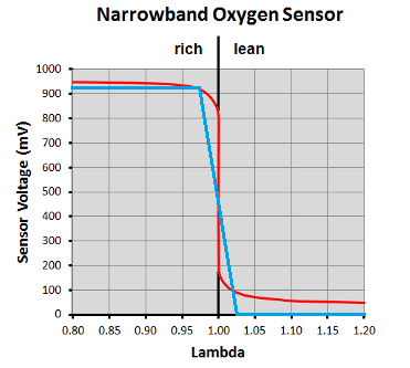
More or less, I programmed the 0-5V output with the USB serial commands as per the user instruction manual, using the commands set SETLAM5V to 0.99 and SETLAM0V to 1.00, with a resistor voltage divider. It worked well enough at first, but still get the check engine once in a while. Then I’ve tried to set them to 0.9999 and 1.0001 as per @toalan recommendations, and while it reported back 1.00 for both, it did work well enough to stop the check engine light from coming on, but not well enough to clear the permanent code, which will reset anyway, once I’m happy with my tune and put back the original narrowband sensor.

I’ve been tuning for months now, added bigger injectors (Don’t forget to tune the gas pump control module if you have a Trax, to better cope with the additional demand, I had to, gas pressure was dipping low when I went WOT), alcohol sensor, fine tuned the MAF sensor, then realized it was bad (huge hysteresis), replaced it, tuned it again, then tuned the VVE tables, then the virtual torque maps and accelerator demand, and then the tranny… It’s been a long process, but it’s way more aggressive now, yet have a better fuel efficiency when I drive normally.

Now I’m only using the wideband to monitor the tune, make sure everything runs fine as it should, in any temperature, in all conditions, once I’m satisfied, I will put the narrowband back and be done with it, if I’m ever done with it :wink:

To hook it up, I plugged the 1200 Ohms resistor into the Analog output (screw #6), the 220 Ohms (what I had in stock) to the electronic ground (Screw #2), then soldered the other resistors ends together with the wire going to the ECU, which gave me the required signal.

You do need to know that I was using the CANBUS signal to read the real wideband sensor value from my MPVI3 with VCM Scanner (HP Tuners), so I didn’t mind sacrificing my analog output since I wasn’t using it for tuning and/or a gauge.

@toalan did mention that he would add better support for both the narrowband and wideband analog outputs in the next firmware, you should check with him what’s the ETA for those modifications.

Hope this helps,
Dr_Evil

1 Like

@Spcbrn, just so you know, how I hooked it up and made my life a whole lot easier in the process.

I’ve cut the wire of an old narrowband sensor I’d replaced a while back on my car, and used the plug to connect to the car harness.

From that plug 12V, I’ve powered the Spartan 3 module, screws 1 and 3.
Then between that wire and the heater ground wire, I’ve put a 20W resistor to fake the heater for the ECM.
I’ve used the sensor ground signal to feed the electronic ground screw #2 where I also have one leg of the 220 Ohms resistor hooked up.
From a screw on the body, under the dash, I’ve used a round lug, and brought a ground to the heater ground of the spartan 3, screw 4.
And as explained before, the 0-5V output, screw 6, is connected to the 1200 Ohms resistor.
Both resistors free legs are hooked up together to the wire sending the signal back to the ECM, also through the plug.

The reason that I didn’t use the heater ground coming from the ECM it that it conflicted with the Spartan 3 heating system, and threw check engine code for a bad heater. The E78 ECM control the negative side of the heater output to modulate the heater (PWM output) and to check for proper resistance. So the high power resistor fake the heating element, and the ECM stays happy.

So, in the end, I didn’t modify my car harness at all, the only wire added was the one going to the body, and that is about 4" long :wink:

And if I need to switch back to my narrowband quickly, all I need to do is unplug the Spartan 3 from the harness, switch the sensors, then plug back the narrowband sensor, and no one’s the wiser :wink:

Hope this also helps :smiley:

1 Like

Sorry again for the delayed response, the resistors are for lowering the voltage while keeping it linear, also known as a voltage divider.

This way you can take a 0-5V signal and make a 0-750mV signal, by dividing it by roughly 6.45 (1420/220)

I tried to remove the heater warning, but I got a permanent code before I cancelled it, so to clear it I put in the 20W resistor, and left it there.

1 Like

Hi, no worries !

I figured what a voltage divider was after some searches, I guess I could’ve done that before asking you :sweat_smile:

Is there a reason why you targeted 0-750mv instead of 0-1000mv? I used a 1200Ohms and 300Ohms resistors to get the 5V → 1V conversion and it’s working fine on my car

Thanks for your feedback!