I was actually aiming at 850-950mV but had to work with what I had on hands 
It was a pleasure and happy it worked for you too 
I was actually aiming at 850-950mV but had to work with what I had on hands
It was a pleasure and happy it worked for you too
I would like to do something similar but I have a few questions:
These posts are from back in 2022 and latest firmware is 2023… The documentation still indicates strict 4 character input. Is this still true? The NB switch point is 5 characters. 1.08 changelog also mentions NB hybrid mode but I see nothing in the documentation.
Is this still the preferred method?
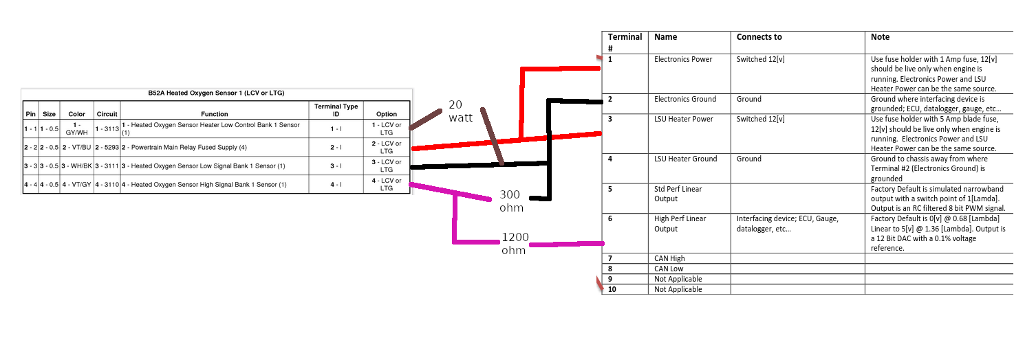
Is this crayon diagram correct?
Thanks!
Hi there SadPanda,
I wouldn’t know if it’s still the preferred method, but it’s the one I still use.
As for the crayon diagram, I would connect the 20 Watts resistor to terminal 4 instead of the electronic ground, and then go from terminal 4 to the car’s body.
The electronic ground is meant to be used as a reference for electrical signals, so using it for a power ground could offset the signal and/or induce electrical noise that you don’t want there.
Now there is something else bothering me about the wiring of the 20W resistor, it seems to be switched on the low side on your car (like on mine), if it’s the case, then the other leg should not be hooked up to the ground at all (terminal 4), but to pin 2 (red wire on your drawing). In either case, terminal 4 should still be hooked up the a ground on the car’s body.
Hope this helps ![]()
Thanks for the quick reply.
Good catch on the 20w… I had it correct on my hand drawn crayon diagram but biffed it when I did the digital in gimp.
Is there some trick to bench USB programming? Either I’m missing something or I’ve got a defective unit.
To access USB serial commands on the bench, leave the sensor disconnected, Screw terminal pin 1 to 12v, Pin 2 to ground, Pin 4 to ground.
toalan - thanks for the responses. Per your email, both grounds AND both 12v power connections got me going.
Two followups - after setting LAMFIVEV and LAMZEROV per recommendations above, both GETs return 1.00v - Safe to assum the four decimal place firmware mod only made it to the input command not the output?
What CAN baud is recommended for HP Tuners pro cable? I’m having trouble finding a maximum baud in HP Tuners documentation, only settings in VCM are polling frequency which is defaulted to ‘0 - fastest’
Thanks again.
Yeah, I never ended up adding more decimal places.
I think for HPT, the default BAUD rate of 500k is what people use. I do not think the polling rate affects Spartan 3 as Spartan 3 sends data at the rate specified by the user, the default is 20 times a second.
Got everything wired up but hit a snag - Grounding pin 2 through O2 sensor low is not working. Grounding voltage divider there is working fine but adding pin 2 the spartan3 does not power up.
Is it ok to chassis ground both the heater and electronics circuit long term? How far away do I need to get them? I have the heater grounded to an unused stud under my center console, there is a second unused stud in the same area but only 3-4in away. I could string a ground to an OE terminal in the driver foot well area (instrument panel ground according to manual) if that would be better.
Thanks
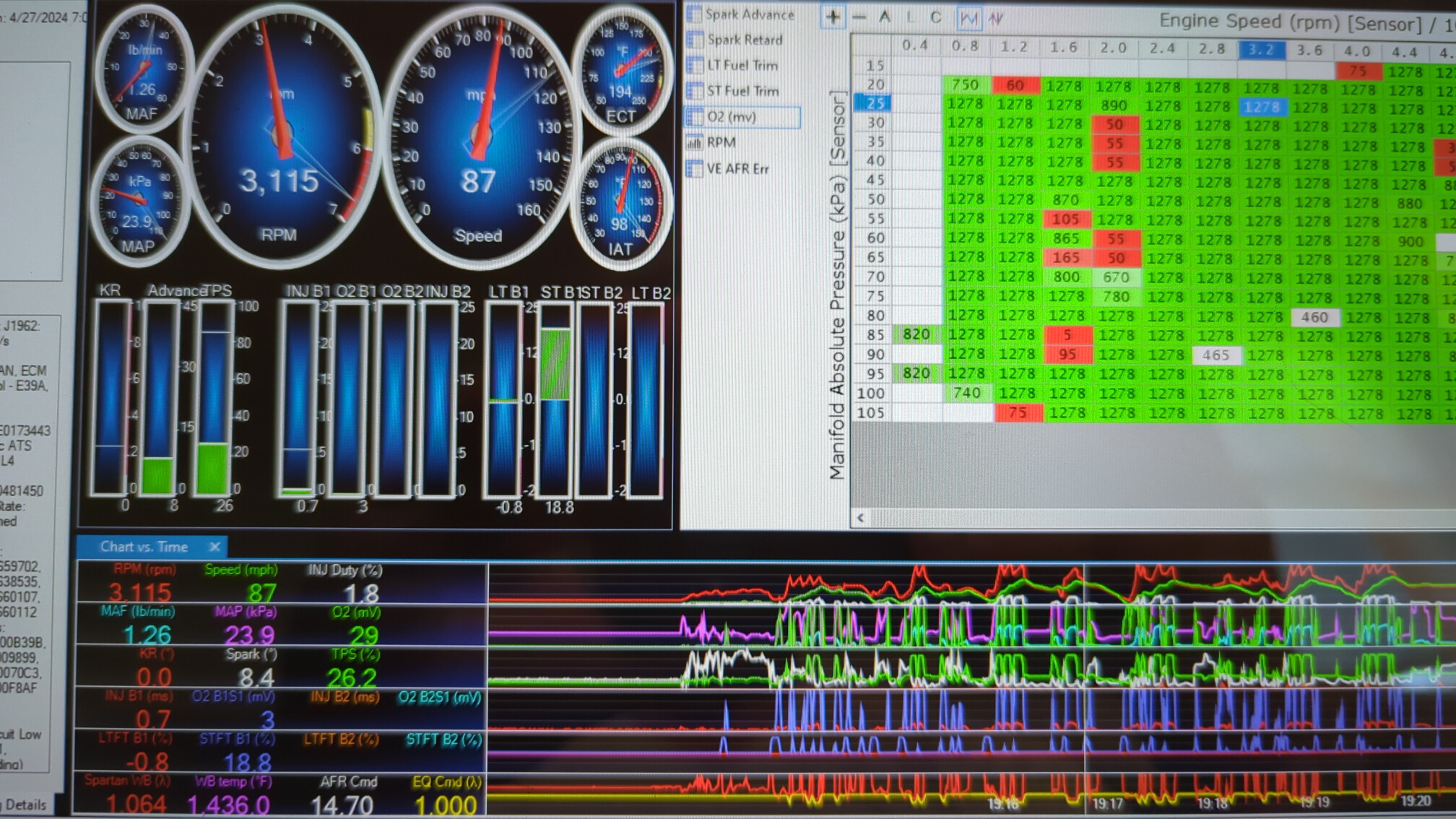
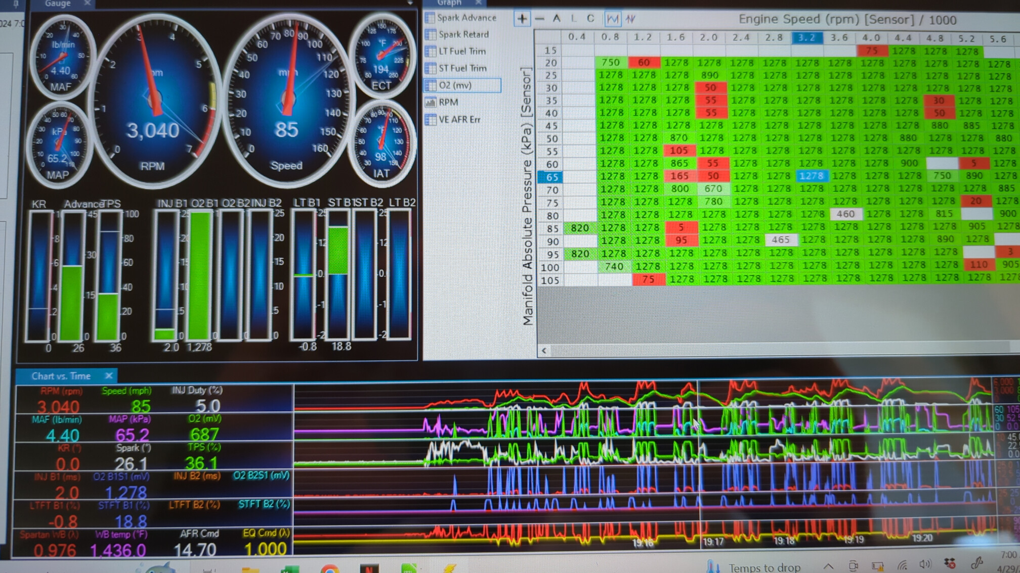
Well, I thought it was working… see attached.
‘O2’ seems to be working albeit a bit slower than the HPTuners sample log, but ‘B1S1’ doesn’t look right at all.
May be doing this all wrong - from HP Tuners stickie
Analog Outputs
the Positive lead will go to your Narrowband O2 “High Signal” line.
the Negative Lead will go to 2 places. Narrowband 02 “Low Signal” and to the Battery Ground.
the reason for this is that the PCM is looking for an 02 sensor…if it doesnt see a hard ground(the narrow band o2 grounds the low side thru the chassis) then you wont have any readings and the pcm will show a constant 450mvIt is Imperative that you take all Grounds back to the Battery Ground.
This will eliminate any ground loops and any ground offsets you may encounter if you decide to ground things in another manner.
Regular NB output on startup then idle
Spartan pin 2 > battery gnd, voltage divider gnd connected to ecm sensor low:
Tried connecting voltage divider gnd and pin 2 to battery ground and unit fails to power
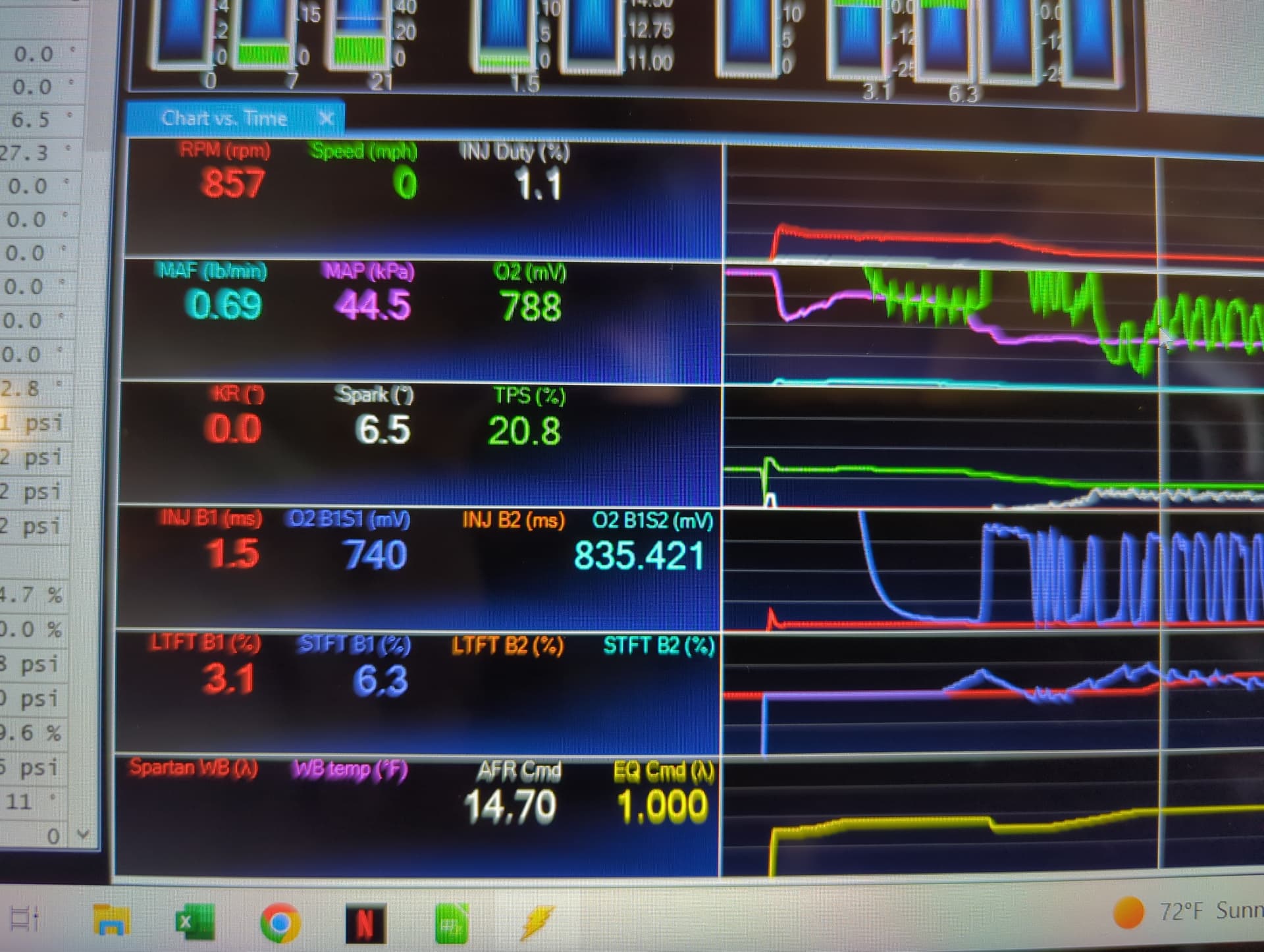
ok back to basics with a DMM - no voltage divider, spartan not connected to ecm in any way.
Spartan3 powered up and sensor connected I’m getting >5v on pin 6, >1v on pin 5 - as expected.
On vehicle, pin 3 ‘signal low’ never gets continuity to ground, rather the opposite - If I probe to ground ‘signal low’ is showing .96v ‘signal high’ is showing 2.7v and if I go across the two (neg on meter connected to ‘signal low’) I’m getting 1.8v
Spartan3 powered up sensor connected, ‘signal high’ connected to pin 6 nothing. ‘signal high’ connected to pin 6, ‘signal low’ connected to battery ground, nothing.
What I’m thinking is A) cant ground to ECM B) signal high / signal low are acting like opposites?
This has got to be something really dumb because it should just “work”
Spartan 3 Screw terminal:
Pin 1 and 3 to switch 12v, can tap from the same spot usually I recommend the fuel pump relay
Pin2 ground to where the ECU is grounded, Pin 4 ground to chassis.
Pin 5 connect to ECU narrowband input
Tried both pin 5 and pin 6 through voltage divider…
While watching scanner in real time, O2B1S1 reads 3mv constant, NOT the expected 450ish waveform, O2 field ‘reads’ but is constantly spiking 3mv and does not ‘pattern’ at all like it does hooked to NB. Furthermore, O2mv does not track with lambda at all, in fact after a while the reading is inverse - sometimes significantly like 3mv with >1 lambda
The only variable left would be my extension harness. Rather than cut the NB o2 connector I got an 18in extension harness, cut the sensor side connector off and extended that with 16ga primary wire crimped/heatshrink ends into the interior. Even if this harness was introducing inaccuracies, the pegged 3mv is still not right.
why are you using a voltage divider?
If you are using the simulated narrowband output, Pin 5 on screw terminal, you do not need to use a voltage divider.
Give me some credit here… I’m not using it like that. In an effort to get SOMETHING working I have tried both pin 6 through voltage divider (with changes mentioned via usb terminal) AND pin 5 by itself.
Hi sadpanda,
Looking at those voltages on your pictures, I’m guessing you either used the wrong resistor values, or you swapped them, those values are way too high. Voltage reading should never be above 1V (1,000 mV), and actually should be at 850-950mV at max.
5V * 300 Ohms / (1200 Ohms + 300 Ohms) = 1500V Ohms / 1500 Ohms = 1V or 1,000mV
Thing is that some ECU may detect 1,000mV as a “bad O2 sensor because the signal is too high”, this is why I used a bit lower than 300 Ohms, as my low value, to make sure I’m under 1,000mV, but 1,278mV is definitely way too high. Either that, or the ground used for the reference is bad, and add some undesirable resistance.
You said that the Spartan failed to power up using the gnd from the O2 sensor plug, this is strange, maybe there is some kind of filter inside the ECU that you’re fighting with to make it work? Have you checked your electric ECU schematics?
What might also be the case, is that your ECU might be reading the low side of the sensor, instead of the high side, the high side being the reference *regulated voltage", if that’s the case, your reading would be inverted, and you wouldn’t be able to power the spartan using the low side. If that’s the case you would need to make some changes on the voltage divider side, using an op-amp circuit, to pull down and invert the signal, using the high side as reference, likely an inverted differential amplifier combined with a voltage follower to prevent sending back voltage into the high side when the value gets greater than the reference (even a schottky diode would have too high of a forward voltage drop), unless the 0-5V analog output has pulldown capabilities.
Another way to make this would be to use a transistor, since we are basically only switching, but I would need to know the reference voltage (O2 high side) beforehand, to design the proper circuit.
Hope this help ![]()
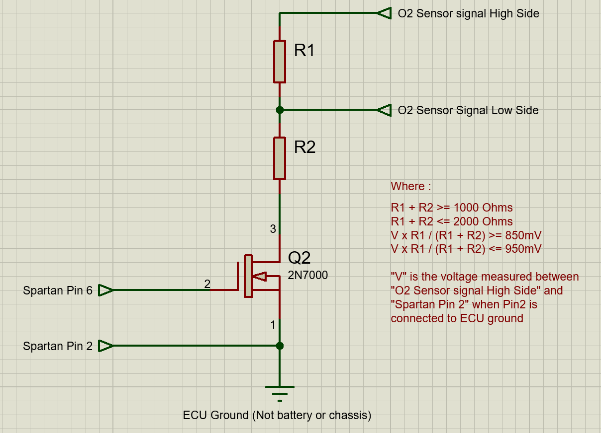
Since I strongly suspect that the problem you’re having is that the ECU is reading the low side instead of the high side, I went ahead and draw the schematics of what would be needed to fix the problem.
This will also invert the signal, so, if it doesn’t work as it should, switch the 2 values in the Spartan program (Setting SETLAM5V to 1.0001 and SETLAM0V to 0.9999 will invert the signal)
The Mosfet I picked up is very low cost, and should work really well in this case.
Hope this helps too ![]()