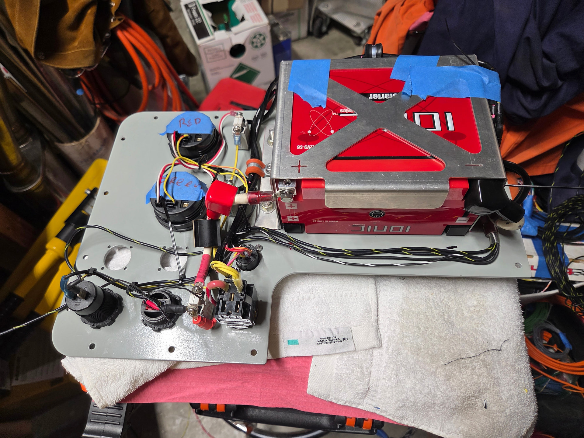
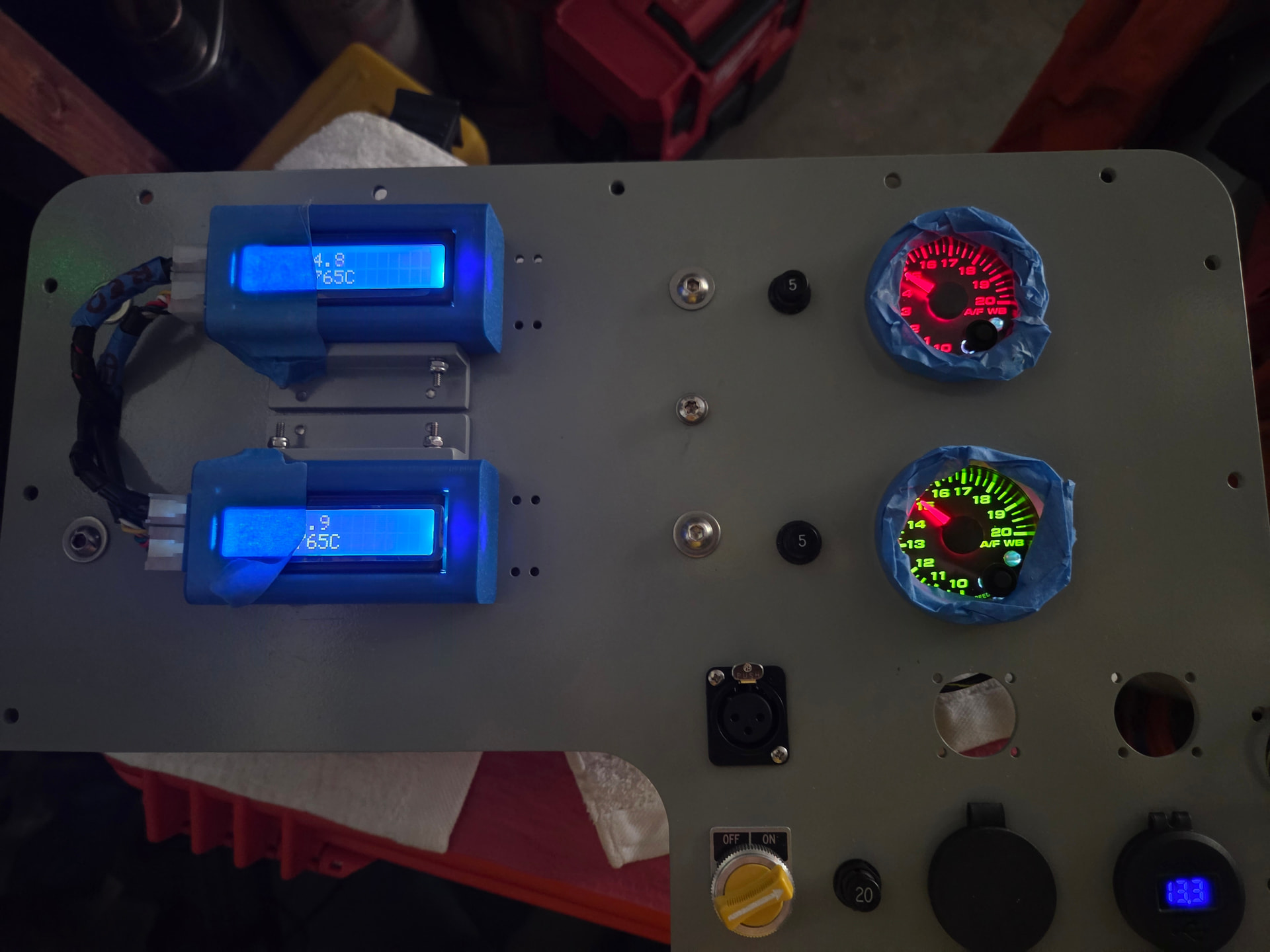
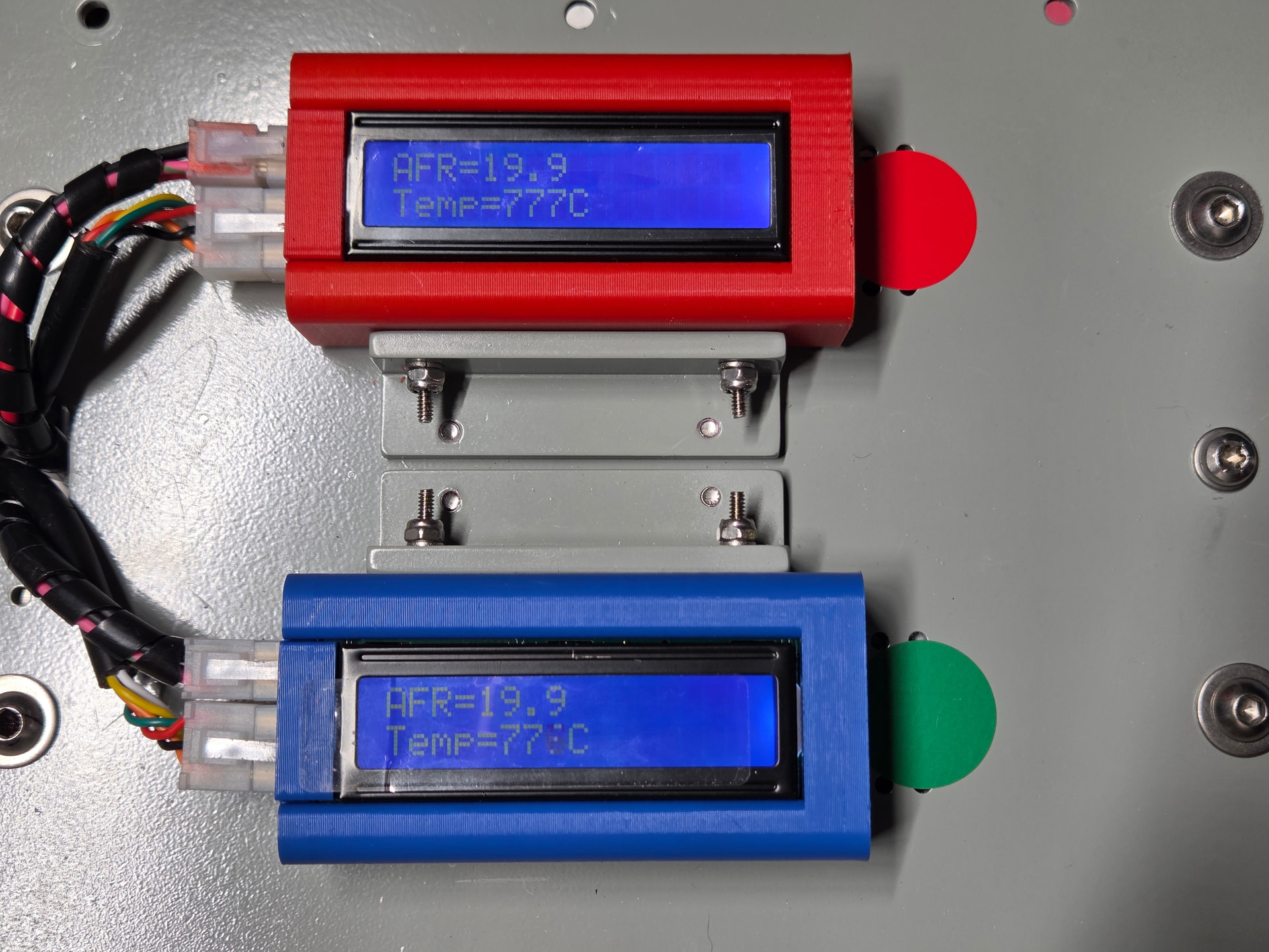
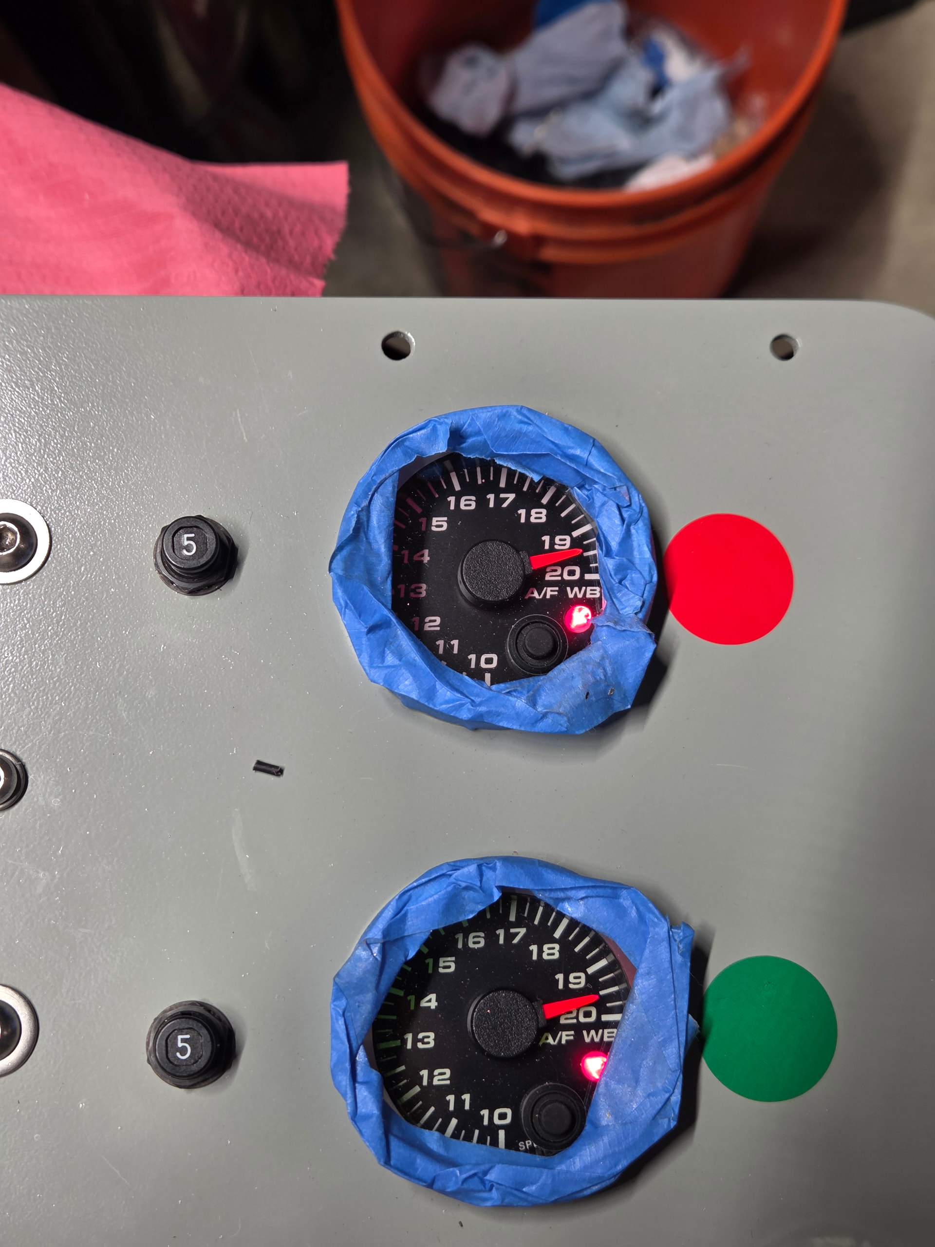
Just got the tail pipe sniffer project fired up with both the SLC Free 2 and some new SpeedHut AFR gauges.
With the sensors in free air the digital is reading 19.9 AFR, The Gauge is reading 19.5. I don’t have a stable way to check it at another fixed value (Mid range). I looked at the voltage at the output of the SLC2 (I added a jack to monitor) and what I’m seeing is 4.765V and 4.753 with both 4.9 sensors in free air. The gauges as I think they should be calibrated 5.0V is 20 AFR on the SpeedHuts. I changed which gauge is on what controller and you can just see the little difference move from one to the other so I think they are reading correctly, but the SLC’s digital is different then the analog.
Is this caused by the heater offset on the analog line like the mod you have pinned at the top of the forum? I have pretty recent boards, and not sure if the mod will fix/help the offset I’m seeing.
Everything on the Ground side of the wiring is star grounded to the battery ground, SLC’s grounds are thick and pretty short if that matters. Voltage is running at 13.1V as the gauge and the battery also show the same (battery has bluetooth biometrics as it might be called…).
Trying to figure out if or how this will affect the 14.7AFR reading mid scale? Or if the fix is the Mod that is posted.
Scratch the comment on the gauge accuracy, totally forgot these are all stepper motor driven so not likely off due to that sort of old school thinking…
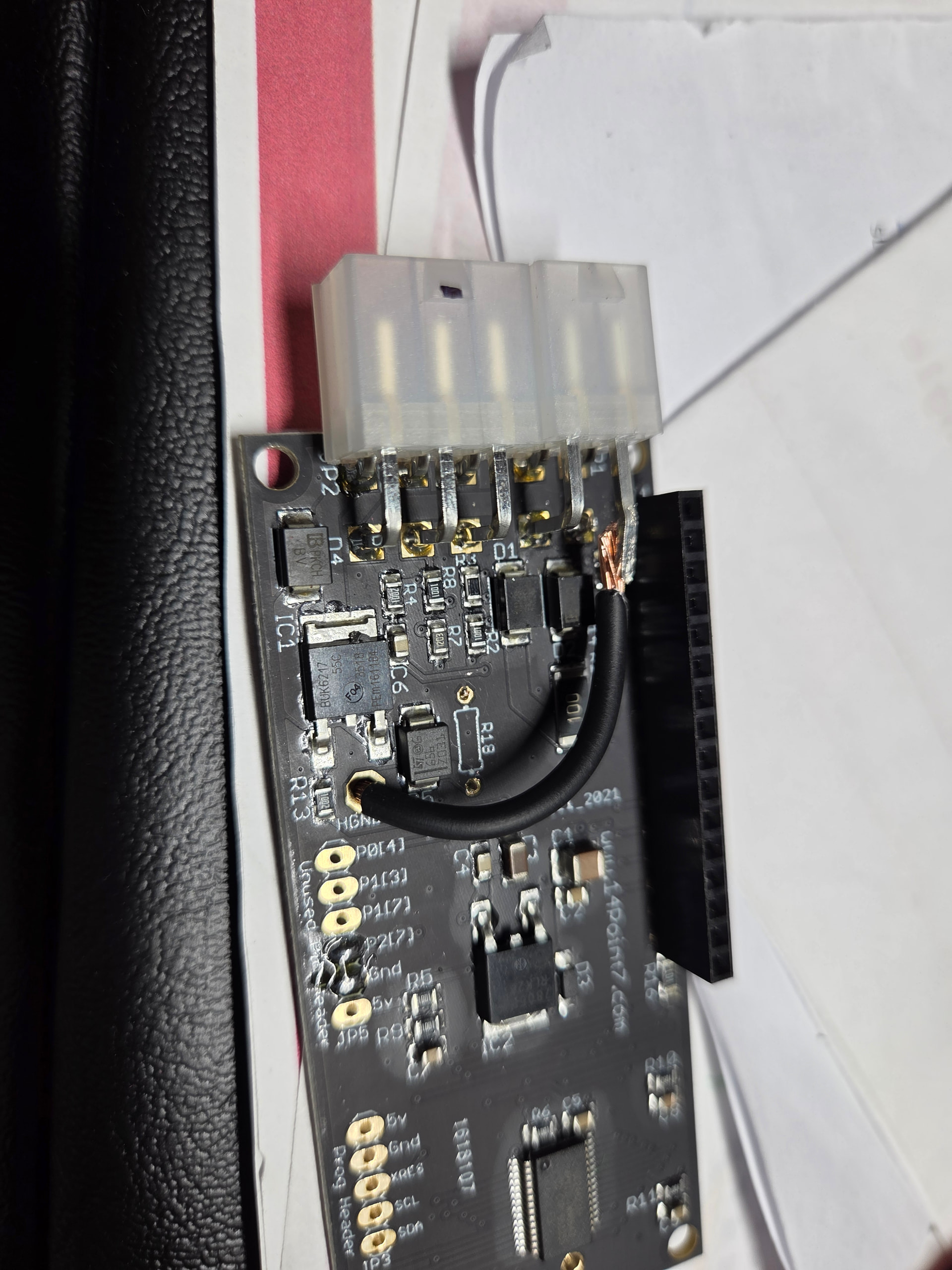
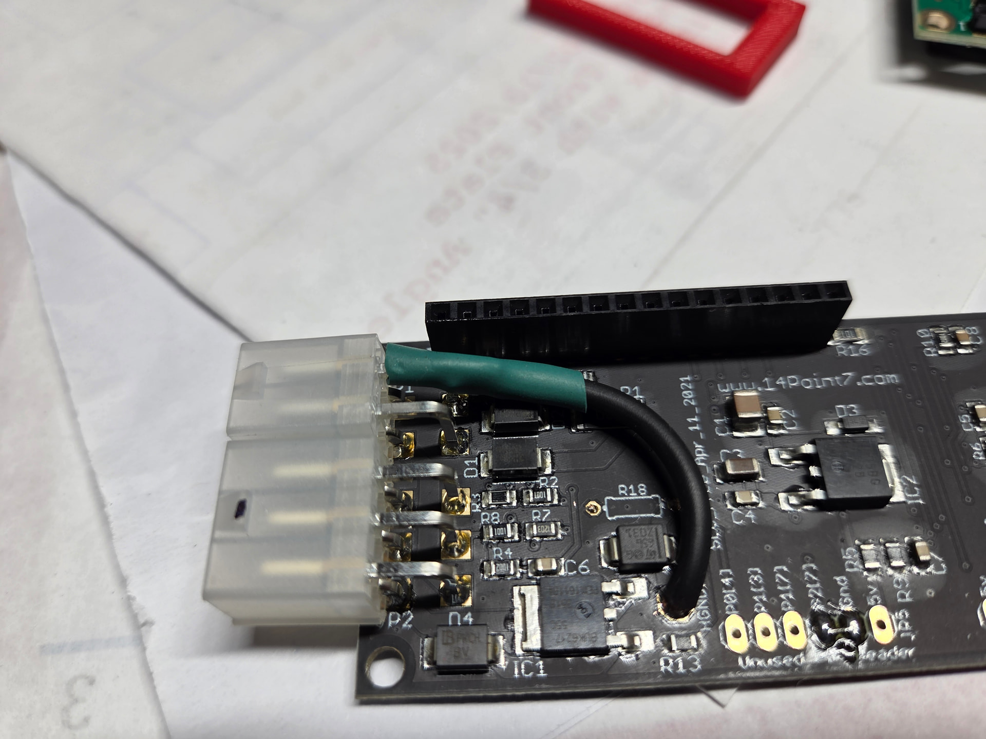
Tried the modification to lifting the ground and running a separate one though the Molex connector. I chopped the connector for the Narrow band off the board, and am now using that for the ground.
This then connects direct to battery ground (ALL are star grounded to a 1/4” bolt, and that goes to the battery via a very short #4 wire) and not seeing any difference in the Analog output.
As an example the LCD reads 14.8/14.9 and the gauge is reading around 14.5.
The other channel is reading a bit higher but still not correct, and that is without the ground modification.
Tried both with and without the O2 sensor, 19.9 LCD is about 19.5 on the gauge.
What else to try? Seems far enough off to be a problem at this point.
Also what is the expected analog voltage output formula just to double check AFR vs. Volts Out so I can check the gauges??
Going to build another of the boards the same way and see it this is consistent, but seems like 2 have the offset, one without the lifted ground is better then the one with the ground modification…
Just built another SLC2, same way, with the external heater ground. I replaced one of the previous units and now both units are reading the same. The same also having the analog voltage offset, but at least both LCD readings with/without the sensors are matching.
So one of the boards (the one removed from play) has some differences in a parts tolerance or something else going on that makes it read a bit differently. It’s not that far off, but definitely off a bit vs. the 2 other boards that are about the same.
So now 2 boards seem to match, but not the analog output.
Again at 19.9 on the LCD the gauges now both read 19.5, and about .2 or .3 off when the sensor is not plugged in.
Otherwise seems to be operating OK, just not sure how to kill the offset on the gauges.
I don’t think it’s the gauge as at 5.0V the AFR on the gauge is dead on 20.