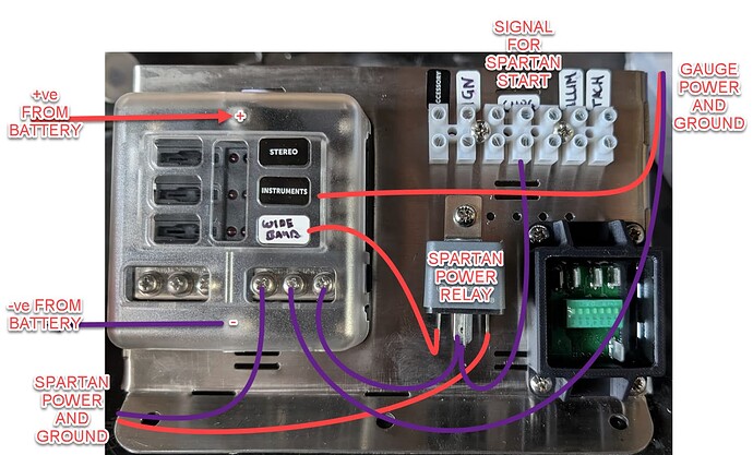
I am in the process of installing a JRP 14/1 Gauges Kit with a Supplied Spartan 3 Lite Module.
This is in a an old car with mechanical a mechanical fuel pump etc. so i have had to work around a few things.
I now have to plan the wiring for the O2 Sensor and Spartan. However I have run a Complete new BUS and Fusebox for the Gauges, Spartan and other Accessories like my aftermarket head unit.
I have run a new line of 8mm2 Twin direct to the battery with a 60amp MIDI fuse and in the car a small 6 way ATS fuse block to individually fuse my devices. This block has a Negative rail also so I’m running both a direct positive and negative from the battery.
Reading my Documentation from JRP and the 14Point7 Documentation i cannot work out the point of the separate heater ground and where I should ground it.
Based on this The spartan controller will not be connected to a chassis ground but a direct ground to the battery on the negative terminal of the fuse block, the same ground will be used for my JRP Gauge Kit. Where do i put the heater (White) wire, just a chassis ground to keep the potential different? I have a few large ground leads from the engine to the battery and the chassis.
any help here would be appreciated before i begin cutting holes or trying to run a white wire extension to the block directly.
UPDATE:
Doing some reading it has do to with there being a lot of noise potential off the white heater ground due to using PWM for the heating.
So if I ground the heater back to the CHASSIS (in my case the trans tunnel) and my JRP Gauge kit and the Spartan Power to the new -ve rail in my little fuse box, the potentials between them and thus the lower level voltage signal (0-5v) for the gauges should not see offset due to noise.
If anyone can provide input here that would be great.
